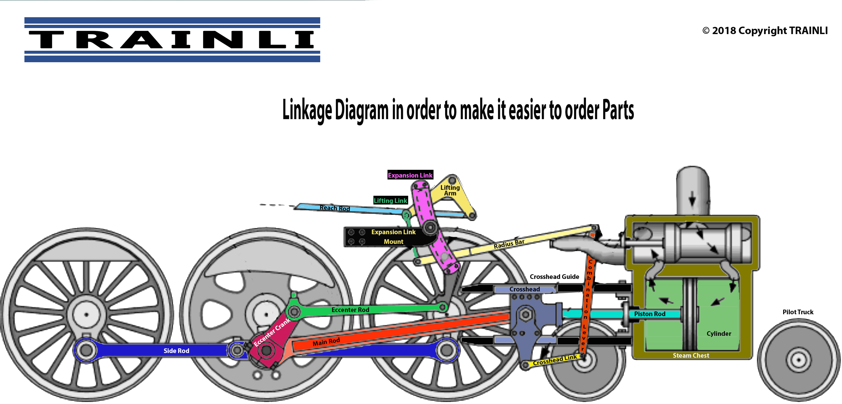
Many customers wonder how to describe a piece of the broken linkage. What is a siderod, versus a pushrod, what is a crosshead? We have below a diagram that names all the important elements. Not every single LGB engine (or USA Trains, Accucraft, HLW, ….) have all the parts that are in our details. The diagram is based on a Pacific engine 4-6-2. But applies similar to other engines as well.
The are different type of valve gear used:
Steam in engines was generated from three type of fuel, Coal, Wood, Oil all used to heat up a boiler to set the engine under "steam". Water is added to the boiler by two injectors (one for crew member), or an injector and a feedwater heater. An injector uses steam to force water into the boiler, heating the water as it does so. Water from the injector is still cold compared to that in the boiler, so the check valve where it enters the boiler is placed forward, so as not to cool the water near the firebox. More efficient feedwater heaters, fitted to most large locomotives after the mid-1930's, use exhaust steam to preheat the water.
Some engines have pilot trucks and/or trailing trucks all indicated by the first and last digit of a 3-digit sequence 0-4-0, 2-6-0, 4-8-2. An 0-4-0 engine has no pilot nor trailing wheels and a 4-8-2 uses a 4-wheel front truck as the pilot wheels and a single axle truck as the trailing truck.
